
Optical CMM Inspection Services: Fast and Accurate Part Inspection
There are cases where a traditional coordinate measuring machine, or CMM, is not the right tool for the job. An optical coordinate measuring machine, or optical CMM, makes use of non-contact measurements, which can enable the measurement of flat parts, small features, and flexible materials. Traditional CMMs excel at 3D measurements, while optical CMMs are equipped to measure both 2D and 3D features. Because of this, we now offer optical inspection services to our customers throughout the Puget Sound region.
Our multisensor optical CMM has both a camera sensor and a touch probe, allowing a greater variety of part geometries to be inspected with a single measurement system. Automated inspection is made possible by computer-controlled motors and repeatable algorithms. If you are interested in learning more about how our optical inspection services can benefit your parts, visit our Contact page to begin a discussion.
What is an optical CMM?
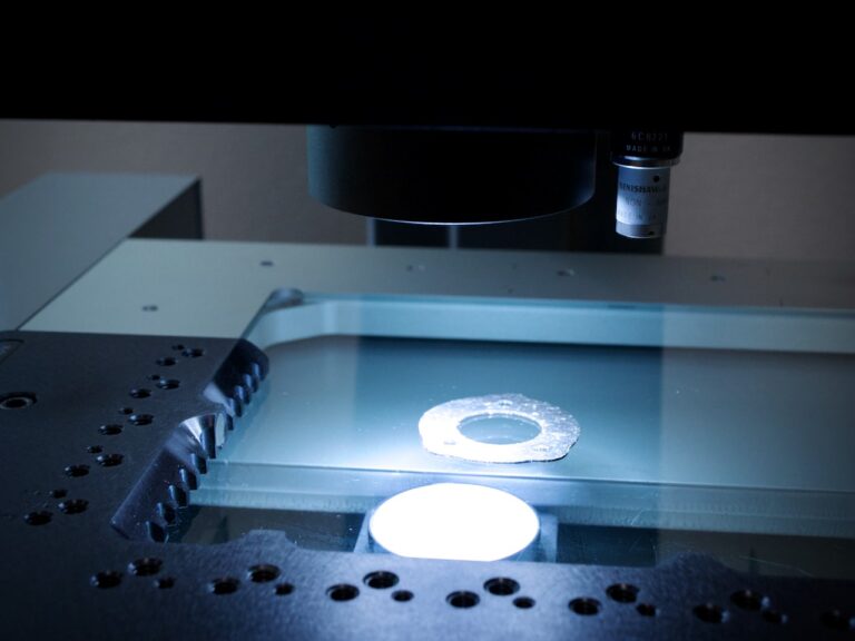
Optical coordinate measuring machines, or optical CMMs, are machines built to measure points in 3D space by moving a camera sensor along 3 perpendicular axes. They are like conventional CMMs in many ways, but they do have some unique characteristics:
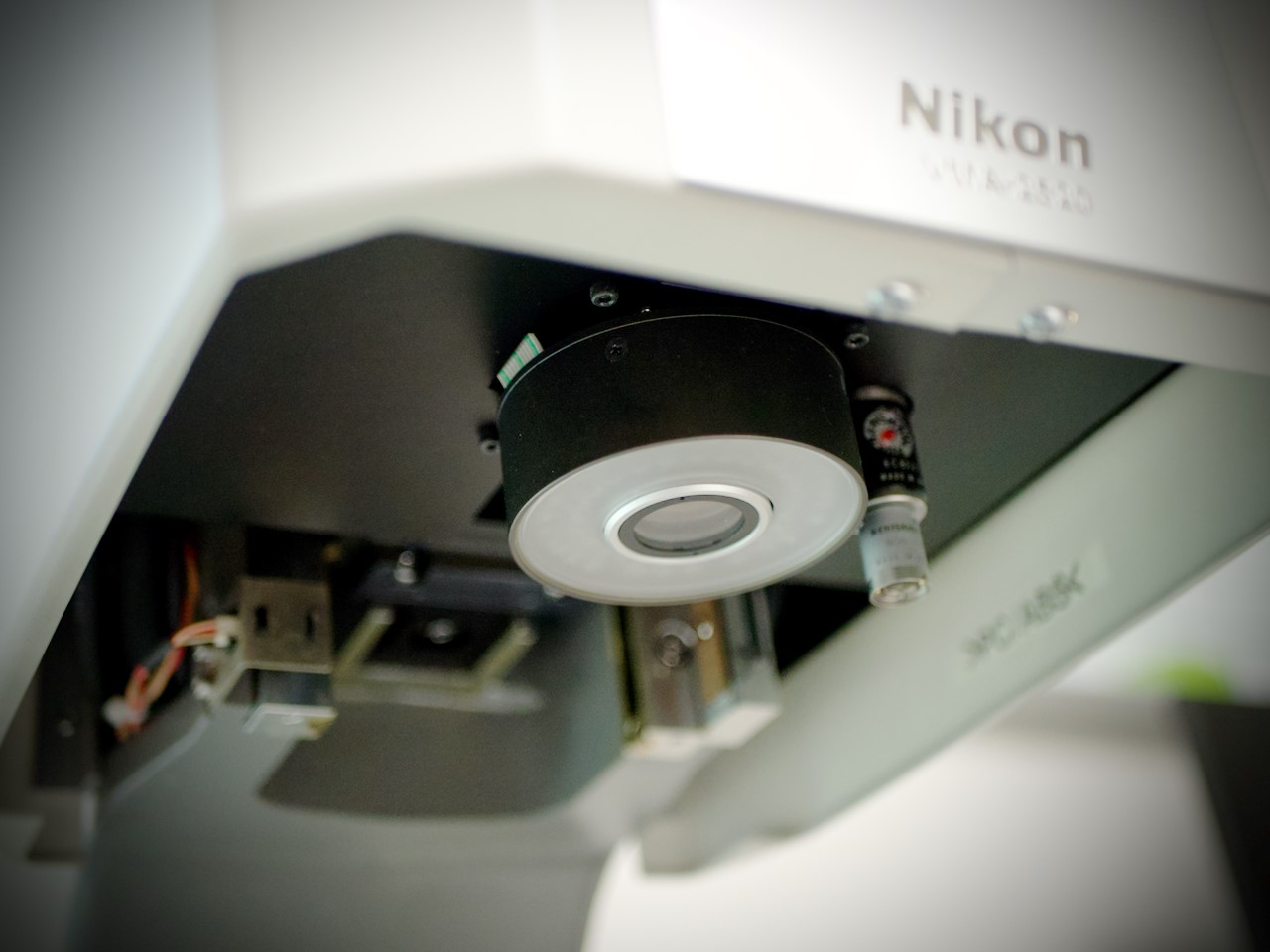
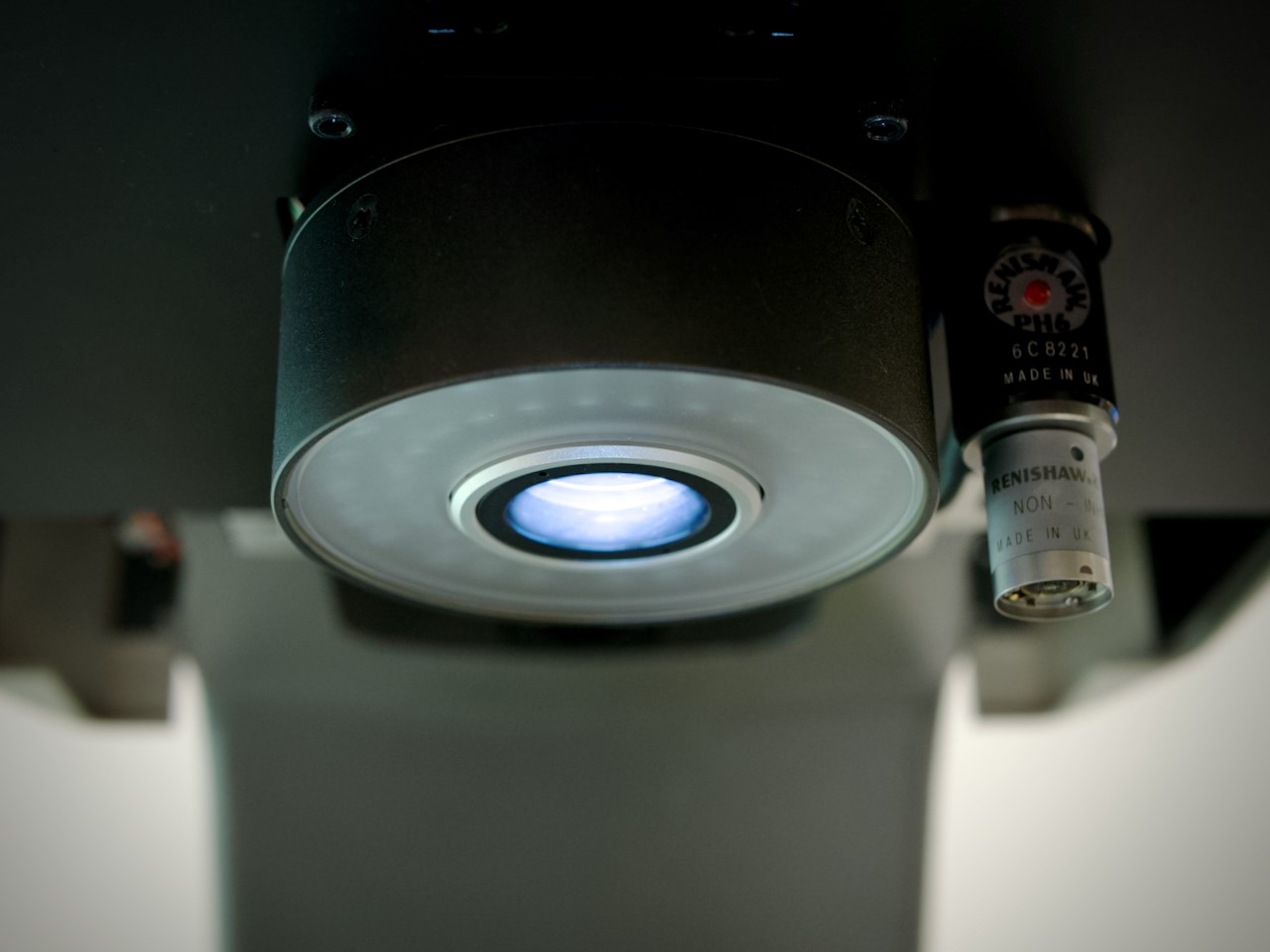
– A camera sensor mounted to the vertical axis
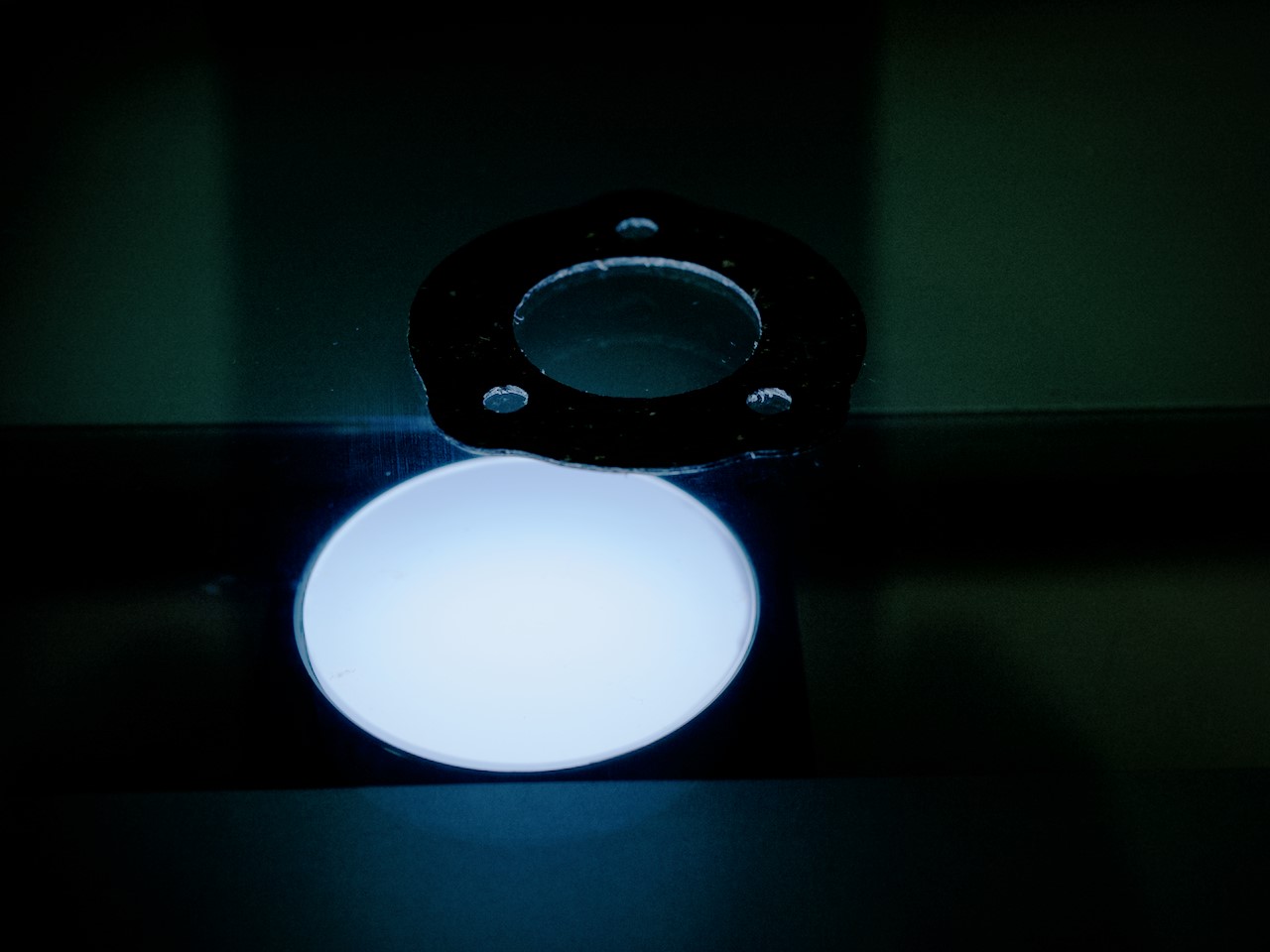
– A glass measurement stage for holding the part or assembly
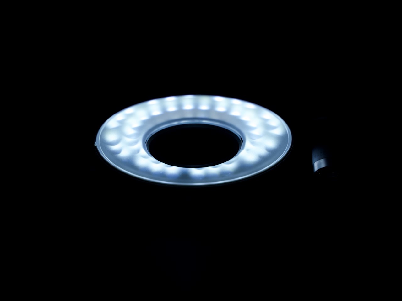
– Various lighting options to illuminate the part during measurement
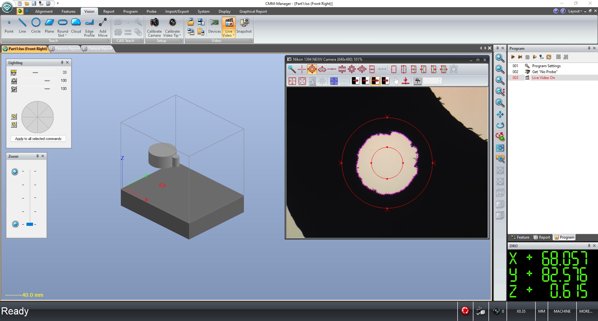
– Special software to receive the camera image and extract measured points from the image
Measurement Sensors Available for Optical CMMs
Although the primary sensor used on an optical CMM is a camera, they can also come outfitted with many types of measurement sensors. Common sensor types include touch probes, lasers, chromatic confocal sensors, interferometers, and low-force touch probes.
Our optical CMM includes a Renishaw TP20 touch probe, enabling more accurate measurements on three-dimensional features.
Many names for the same measuring device
Depending on who you ask, you may hear many different names used to describe optical CMMs. Other common names for optical CMMs include:
– Optical measuring machine (OMM)
– Multisensor measuring system
– Multisensor CMM
– Vision system
– Video measurement system
– Vision measurement system
– Vision measuring machine (VMMs).
Easily measure thin, flexible parts and tiny features
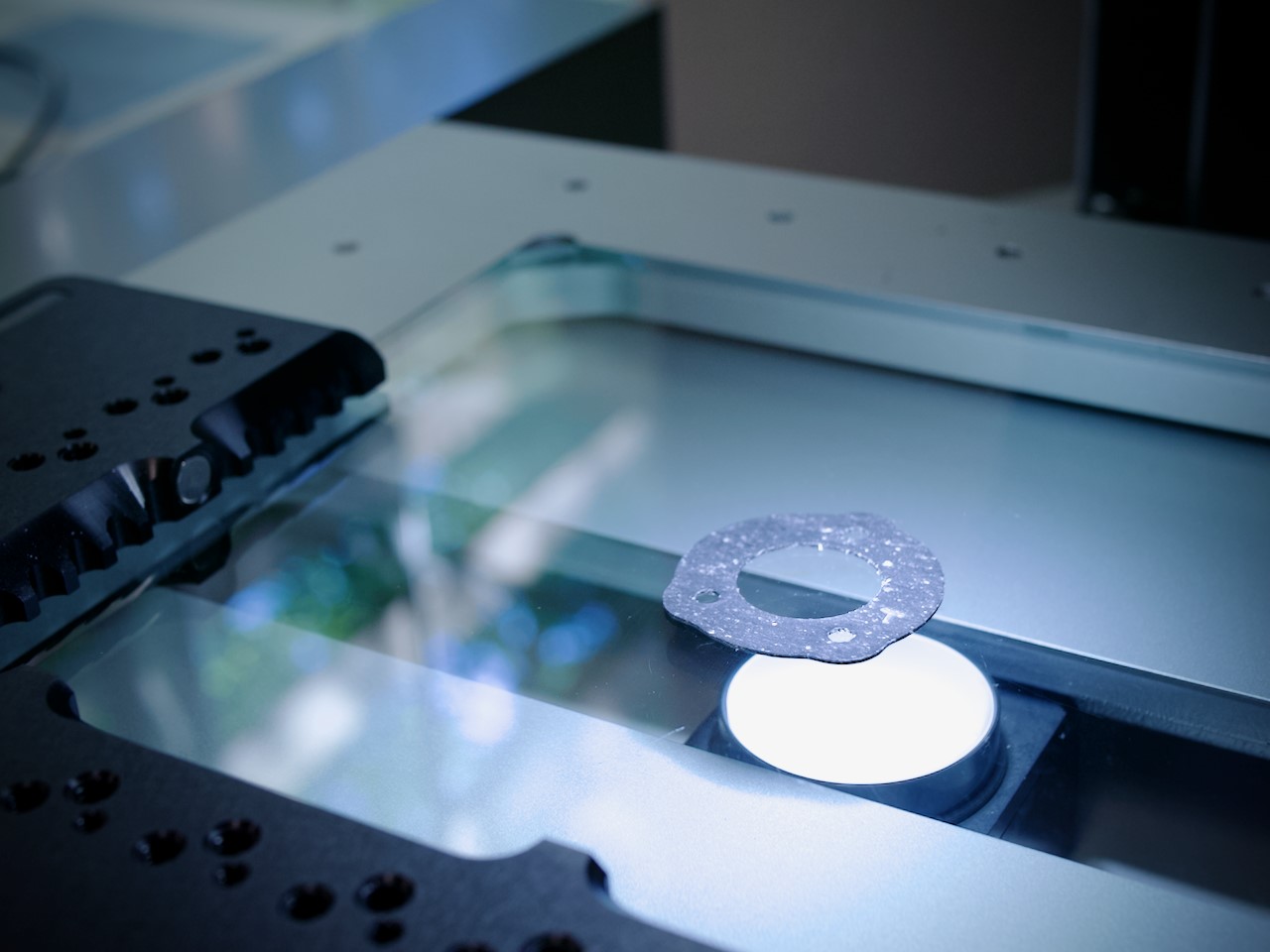
Because of the unique designs of optical CMMs, they tend to be better at measuring flexible, flat, or highly detailed parts when compared to their conventional CMM counterparts.
– Flexible parts that may bend or deform when measured with a touch probe
– Flat or two-dimensional (2D) parts that don’t have enough thickness to be measured with a spherical probe
– Flat, printed, or 2D features that are visible, but don’t have enough depth to be measured with a touch probe
– Tiny features too small to be measured with touch tools
With these benefits in mind, one can start to realize the many potential applications for an optical CMM. Some examples include:
– Gaskets and seals
– Consumer electronics parts like printed circuit boards (PCBs), printed circuit board assemblies (PCBAS), flexible flat cables, and connectors
– Sheetmetal parts
– Laser-cut or waterjet parts
– Parts with holes < 1mm in diameter
– Portable device frames, midframes, and housings
– Assembly gaps
Our Vision and Touch Measurement Tools
Nikon iNexiv VMA-2520
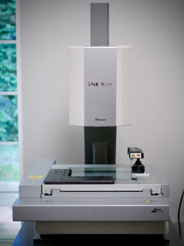
For hardware, we use a Nikon VMA-2520 vision measuring machine. This multisensor system provides a balanced set of features and can measure many types of parts and assemblies.
| Measuring volume* | 250 (X) x 200 (Y) x 200 (Z) mm 9.84 (X) x 7.87 (Y) x 7.87 (Z) inches |
| Maximum permissible length error** | EUX,MPE EUY,MPE: 2+8L /1000 μm |
| (L = Length in mm) | EUXY,MPE: 3+8L /1000 μm EUZ,MPE: 3+ L/50 μm |
| Camera sensor | Color 640 x 480 pixels |
| Maximum field of view size | 13.3 × 10 mm 0.52 x 0.39 inches |
| Minimum field of view size | 1.33 × 1 mm 0.052 x 0.039 inches |
| Working distance (distance from the lens to the focal plane) | 73.5 mm 2.89 inches |
| Touch Probe | Renishaw TP20 with a maximum stylus length of 60mm |
*Not all parts that fit within this measuring volume are able to be measured with this machine. Contact us to learn if this machine is the right fit for your application.
** Nikon’s in-house test at 20°C ±0.5k
CMM Manager
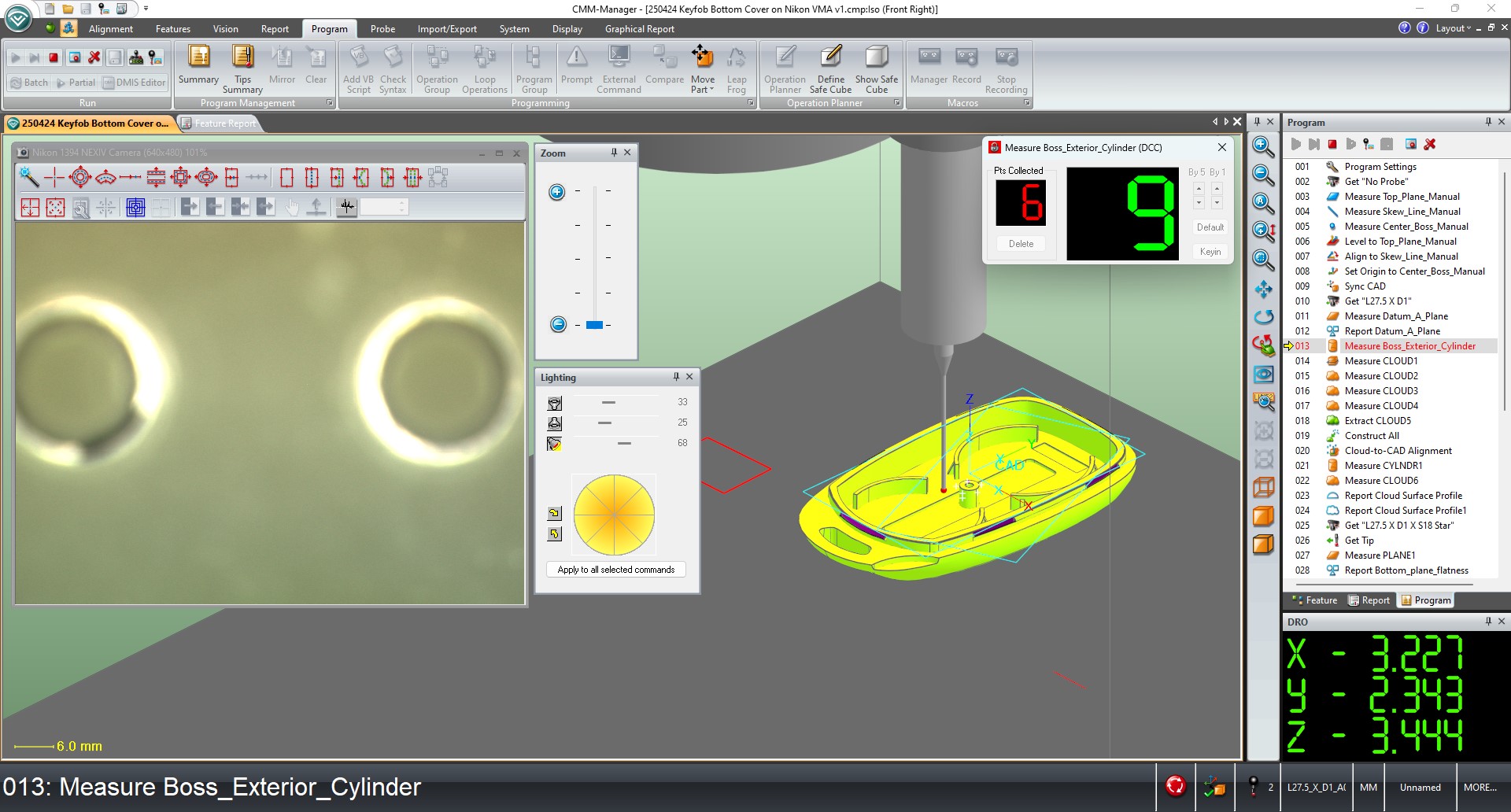
Our Nikon VMA-2520 vision system is paired with the latest version of CMM-Manager. This software is a versatile CMM software also capable of controlling Nikon optical CMMs. 3D CAD models can be imported, empowering more efficient programming and the evaluation of more complex geometric tolerances.
PolyWorks Inspector
Calculate the Rough Cost of Your Inspection Project
Although calculating the cost of your optical CMM inspection project isn’t as clear-cut as other services we offer, we’ve built a tool that will at least give you a rough idea.
Note: Optical CMM inspections sometimes require a custom fixture to be designed and manufactured. Additionally, a specific stylus may need to be ordered for your application. These costs are not included in this calculator.